

ZW - LZ seriesLeft to right out of metal tube float flowmeterIs based on the float position measuring a variable area flow meters, suitable for measuring the liquid and gas.Adopts full metal structure, the concept of Modular design, because of its small size, small pressure loss, large range than (10:1), installation, maintenance is convenient wait for a characteristic, has the 0 to 10 ma, standard 4-20 ma analog signal output and instructions (optional).Local display instantaneous, accumulated flow, digital communications, field measurement parameters, have different ways of power function.
Second, the structure and working principle:
1, the structure:
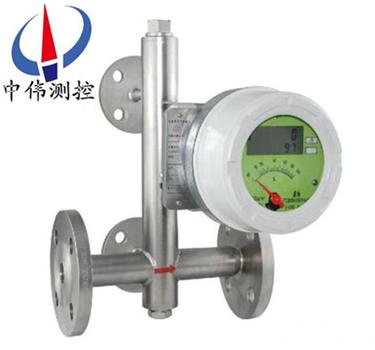
ZW - LZ seriesLeft to right out of metal tube float flowmeter is mainly composed of three parts:
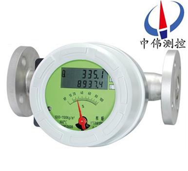
A, indicator (intelligent indicator, on-site indicator);
B, float;
C, tapered measuring room.
2, how it works:
Bottom-up measured medium by the conical float to the top and bottom side of the differential pressure measurement of a tube formed upward force, when the float upward force is greater than the baptism by float weight in the fluid, float up, clearance area increase, immediately drop the gaps in the fluid flow, float up and down the differential pressure is reduced, on the float upward force as well as to reduce, until the upward force equal to the float weight immersed in the fluid, the float is stable at a certain level.The discretion of the float position that corresponds to the size of the measured medium flow.Move up and down in float float the built-in magnet steel, medium, magnetic field changes with the movement of the float.
Type a, for in situ by in situ indicator of the rotating magnet steel and the float inside the magnetic coupling, and turning, drives the pointer at the same time, through the dial indicates the size of the flow at this time.
B, for intelligence, an intelligent indicator in the solid state magnetic sensor to the change of the magnetic field into electrical signals, after A/D conversion, microprocessor, D/A output, LCD liquid crystal display (LCD), to show the size of the flow rate and cumulative flow.
Applications:
ZW - LZ seriesLeft to right out of metal tube float flowmeterWidely used in petroleum, chemical, power, pharmaceutical, food, water treatment, etc.Is complex, condition of bad environment and conditions in the process of the flow measurement of various media.
Four, product structure:
1, adopts full metal structure, there are regular, damping, high temperature and high pressure.
2, according to the customer, sounding pipe structure can be divided into: in the out, down into the cross out, cross into cross out, right to left, left to right.
3, this series of metal tube float flow is mainly composed of two parts: the measuring tube and indicator.Sounding pipe including the taper pipe or orifice plate, guide, stop, float parts, such as indicator including magnetic servo system, a pointer, dial, lines and other components.
Five, the transformation indicator:
Converter is actually change the height of the cone tube float into the corresponding scale of volume flow.On the output signal of points: there is local display and remote transmission signal output:
1, on-site display type: by in situ indicator of follow-up magnetic steel and the float inside the magnetic coupling, and turning, at the same time, through dial, electric pointer indicates that traffic at this time.
Type 2, intelligent remote transmission, by intelligent indicator of follow-up magnetic steel and the float inside the magnetic coupling, and the rotation, sensing magnetic steel and pointer at the same time, through A magnetic sensor to magnetic field changes into electrical signal, after the A/D conversion, digital filtering, microprocessor processing, D/A output, LCD liquid crystal display (LCD), to show the size of the instantaneous flow and cumulative flow.
Six, the main features:
1, all metal structure, strong stability, suitable for high temperature and high pressure, strong corrosive medium.
2, adopts full isolation design, imported from relay output, to ensure reliable operation.
3, in various industries of gas and liquid measurement, measurement part can use different material to adapt to different conditions of medium.
4, vertical, horizontal, all kinds of installation method is more suitable for different occasions.
5, magnetic coupling structure to ensure that the data transmission, signal is more stable.
6, add the magnetic filter, can design with insulation or jacket.
7, vertical, horizontal, all kinds of installation method is more suitable for different occasions.
Eight, can be used in inflammable and explosive dangerous places.
Seven, the technical parameters:
Measuring range: water (20 ℃), 2.5 150000 l/h, air (20 ℃ and 0.1013 MPa) 0.07-4000 nm3 / h.
Range than: 10:1;
Accuracy: 1.5/2.5;
Working pressure: 6.4 MPa or less;
Working temperature: - 40 ~ 350 ℃ (fluorine plastic lining - 10 ~ 80 ℃).
Ambient temperature: - 20 ~ 80 ℃;
Medium viscosity, DN15, or less DN25 ~ 6 or less;
Tube body material: 1 cr18ni9ti, 316 l, lining PTEF, etc.;
Installation method: flange, or according to customers;
The basic error: 1.5%;
The output signal: 4 ~ 20 ma;
Load impedance: 350 Ω;
Power supply: 24 VDC;
Electrical interface: M20 x 1.5;
Explosion-proof marks: ExibIICT4.
Eight, product maintenance:
1, in the long-term use process, the pipe will inevitably have a ferromagnetic impurity adsorption on the float, it would float jammed or affect measurement accuracy, need to clean them often float inside the sensor;If the installation of magnetic filter, also want to make regular cleaning.
2, instrument indicator is equipped with electronic components, instrumentation connection or remove the shell and the screw to tighten, must ensure that shell sealing, to prevent impurities, or other material into the water, but also ensure the reliable earthing of the instrument housing.
3, meters installed, in * times when using, should pay attention to:
Open valve to avoid pressure impact spacing device to float against, causes the damage of instrument, must open the valve slowly!
Measuring gas meter is equipped air damper, zui to large extent reduce the oscillation of the float;In order to ensure the stability of float, and can be installed in the export of instrument a throttle valve.
4, for remote transmission type instrument, first of all to ensure the instrument connection right after, can live;For the dangerous situation, must choose explosion-proof type, use and install according to the requirements of explosion-proof.
Nine, the classification of the structure:
1, high temperature structure type (G)
High temperature structural type (G) is used for medium temperature is too high or too low and need to measure the rate of flow of pipe heat preservation and heat insulation measures of medium measure.High temperature structure is increased the measuring tube and the distance between the indicator to increase heat dissipation, increasing the thickness of insulation material, ensure the indicator work in allow ambient temperature range.Type selection for the "G".
G type metal pipe flow meter can measure the temperature - 80 ℃ to + 300 ℃ medium flow.
2, the structure of the device with damper (Z)
Damper is structured for flow meter inlet flow (pressure) unstable when the medium flow measurement, especially for the measurement of the gas.
3, the structure of the clamp cover model (T)
Clip model structure used for heating or cooling, such as the high viscosity and crystallization medium flow measurement.In the jacketed by heating or cooling medium, make the low boiling point and low solidifying point fluid evaporation and crystallization.
Import and export of heating medium connection, the standard to use HG20594-97 DN15 PN1.6 flange, other connection flange specification can be indicated with factories, jacketed level of pressure is 1.6 MPa.
Clip model see FA standard flowmeter flowmeter structure flange, dimension drawing.
4, high pressure type structure (Y)
High pressure type structure used for pressure is greater than the standard level of measured medium flow measurement.High pressure type structure as shown in the figure below.The recent series of FFM64 zui high pressure can reach 32 mpa.Additional high pressure type flowmeter can provide built-in magnetic filter, the installation height is 350 mm.FA, FB and FC type z pressure to 10 mpa.
Ten, when installation should follow the following steps:
1, before installation to process piping, should remove all installed and check if there is any transportation damage;
2, to prevent it in transit, are installed in the indicator pointer rubber bands, before connection should be put it gently remove indicator left open, not a pointer position change;
3, open the indicator right cover, cable through the cable device are introduced according to the rotation Angle transducer wiring diagram wiring, screw the nut, the cable is fixed, then tighten the cover around the fastening screw, makes the indicator waterproof dustproof;
4, instrument of the upstream and downstream piping should be the same as the instrument of caliber, connecting flange or thread should be with the instrument flange and match, the gauge length of straight pipe upstream should guarantee is 5 times of nominal diameter, h2 downstream straight pipe length of not less than 250 mm;
5, because the instrument of measuring mechanism USES a magnetic transmission, so in order to guarantee the performance of the flow meter, sensor installation where at least 100 mm, do not allow the existence of ferromagnetic material;
6, instrument before installation, process piping should be purging, are attached to the instrument to prevent retention of ferromagnetic material in the pipeline, affect the performance of the instrument, even damage the instrument. If unavoidable, should be installed at the entrance of instrument magnetic filter;
7, the measuring gas meter, is under particular pressure calibration, if the export of gas in the instrument direct emissions to the atmosphere, will have the pressure drop in the float, and cause data distortion.If this is the working condition, a valve should be installed at the export of instrument, so as to to set the required flow rate value, when float on maintaining calibration pressure, gas puff in the valve;
8, instrument installation forms can be divided into vertical and horizontal installation, if it is a vertical installation form, should guarantee the instrument of straight degree is better than that of 1%;If it is horizontal form should guarantee the levelness of the instrument is superior to 1%;
9, installed in the pipeline instruments should not be the role of stress, the export of instrument and entry should be the appropriate pipe supports, can make the instrument in zui small stress state;
10, the product that is associated with computer operation, calibration, as well as should be carried out in a safe place.
Eleven, troubleshooting methods:
1, check alarm value set size in the SU.
2 d values cannot too big, check the deviation.
The logical function, FUN, whether it is right.HA - A said cap is logical.LA -a said the lower limit is logic
4, circuit board fault, replace the circuit board.
5, if the LCD bar code instructions correct output without action, can check whether the external power supply and external power of the cathode is connected to the instrument power supply of the cathode.
If in use dithering, could be determined according to the extent of jitter is what range of jitter.Jitter is divided into slightly shaking, moderate jitter and violent shaking.
1, the slight shaking: generally caused by fluctuations in medium.Can be used to increase the damping ways to overcome.
2, moderate jitter: generally caused by medium flow state.Is often caused by unstable operating pressure of medium for gas.Can use voltage or current regulator devices to overcome or increase the instrument air damping.
3, intense shaking, mainly due to the medium pulse, pressure instability or users are given gas pressure, temperature and flow of the operating state of inconsistent with the actual state of instrument, have bigger difference meter range.
As long as you use the method correctly, pay more attention to maintain at ordinary times, can ensure the normal use of it.
Twelve, installation considerations.
1, checked out after remove the filler of the flow meter, flow meter should be installed vertically on the no vibration of the pipeline, such as horizontal installation, should additional specifications when ordering.The center line of the flowmeter and the vertical Angle should not exceed 5 °.
2, new pipelines in tube flow meter before installing a new pipeline should be rinsed clean, if the medium to be measured particle impurities or bubbles, filters should be installed in the upstream flow meters or set the outlet, fluid when installation must flow from the bottom up, if the fluid flow from the top down, the meter doesn't work.If measured medium is pulsating flow, should be in the downstream set appropriate size buffer device, such as buffer tank to eliminate pulsation.
3, to facilitate the check meter zero and disassembling maintenance and debugging, the cut-off valve should be installed at upstream or downstream flow meter and the by-pass valve.
4, a meter installed by the regulation, should be closed either upstream or downstream flow meter cut-off valve, check instrument and secondary instrument connection again, and, after open secondary instrument power the instantaneous flow shall display to zero.To normal use, should be open upstream first after the valve is fully open, with metal pipe float flowmeter downstream regulator from small to large, slow flow rate adjustment, the instantaneous flow rate should be changed.Stop working, the upstream downstream of the valve, then close the regulator should be shut down.
13, flow parameter list:
Menstruation (mm) | Flow range | KPa pressure loss | |||
Water L/h * | Air M3 / h * | water | air | ||
The conventional type | Anti-corrosion type | The conventional type, anti-corrosion type | |||
15 | 2.5 ~ 25 | --- | 0.07 ~ 0.7 | 6.5 | 7.1 |
4.0 ~ 40 | 2.5 ~ 25 | 0.11 ~ 1.1 | 6.5 | 7.2 | |
6.3 ~ 63 | 4.0 ~ 40 | 0.18 ~ 1.8 | 6.6 | 7.3 | |
10 to 100 | 6.3 ~ 63 | 0.28 ~ 2.8 | 6.6 | 7.5 | |
16 ~ 160 | 10 to 100 | 0.40 ~ 4.0 | 6.8 | 8.0 | |
25 ~ 250 | 16 ~ 160 | 0.7 ~ 7.0 | 7.2 | 10.8 | |
40 ~ 400 | 25 ~ 250 | 1.0 ~ 10 | 8.6 | 10.0 | |
63 ~ 630 | 40 ~ 400 | 1.6 ~ 16.0 | 11.1 | 14.0 | |
25 | 100 ~ 1000 | 63 ~ 630 | 3 ~ 30 | 7.0 | 7.7 |
160 ~ 1600 | 100 ~ 1000 | 4.5 ~ 45 | 8.0 | 8.8 | |
250 ~ 2500 | 160 ~ 1600 | 7 ~ 70 | 10.8 | 12.0 | |
400 ~ 4000 | 250 ~ 2500 | 11 ~ 110 | 15.8 | 19.0 | |
40 | 500 ~ 5000 | --- | 12-120 | 10.8 | 9.8 |
600 ~ 6000 | ---- | 16 ~ 160 | 12.6 | 16.5 | |
50 | 630 ~ 6300 | 400 ~ 4000 | 18 ~ 180 | 8.1 | 8.6 |
1000 ~ 10000 | 630 ~ 6300 | 25 ~ 250 | 11.0 | 10.4 | |
1600 ~ 16000 | 1000 ~ 10000 | 40 ~ 400 | 17.0 | 15.5 | |
80 | 2500 ~ 25000 | 1600 ~ 16000 | 60 ~ 600 | 8.1 | 12.9 |
4000 ~ 40000 | 2500 ~ 25000 | 80 ~ 800 | 9.5 | 18.5 | |
100 | 6300 ~ 63000 | 4000 ~ 40000 | 100 ~ 1000 | 15.0 | 19.2 |
150 | 20000 ~ 100000 | --- | 600 ~ 3000 | 19.2 | 20.3 |
14, selection of coding:
Code name | Measuring tube structure | |||||||
ZW-LZ50 | In the out | |||||||
ZW-LZ51 | Under the cross out into | |||||||
ZW-LZ52 | The horizontal cross out into | |||||||
ZW-LZ53R | Right into the left out | |||||||
ZW-LZ53L | Left to right | |||||||
ZW-LZ50S | Threaded connections | |||||||
ZW-LZ50M | Quick connector to connect | |||||||
Code name | Answer the liquid material | |||||||
R0 | 0Cr18Ni2Mo2Ti | |||||||
R1 | 1Cr18Ni9Ti | |||||||
R2 | 316L | |||||||
RP | PTFE | |||||||
T1 | titanium alloy | |||||||
Code name | Pipe size | |||||||
DN15 | 15 | |||||||
DN25 | 25 | |||||||
DN50 | 50 | |||||||
DN80 | 80 | |||||||
DN100 | 100 | |||||||
DN150 | 150 | |||||||
DN200 | 200 | |||||||
Code name | Additional structure | |||||||
There is no | ||||||||
T | Clip model | |||||||
Z | Damping type | |||||||
G | High temperature type | |||||||
Y | High pressure type | |||||||
Code name | Indicator combination form code | |||||||
M1 | In situ indicator, instantaneous flow machine instructions | |||||||
M2 | Type power supply, mechanical indicates the instantaneous flow rate, liquid crystal display instantaneous/The cumulative flow | |||||||
M3 | Type power supply, no mechanical indicator, liquid crystal display instantaneous/The cumulative flow | |||||||
code | The power supply mode | |||||||
There is no | onlyM1indicator | |||||||
A | 220VAC,4-20mAThe output | |||||||
B | Battery power, no output | |||||||
C | 24VDC, two wire of power supply,4-20mAThe output | |||||||
D | 24VDC, three, four wire power supply,4-20mAThe output | |||||||
Code name | Explosion-proof marks | |||||||
l | The AnniaCT5Square shell | |||||||
d | flame-proofDiibt4Garden shell | |||||||
Code name | Alarm or pulse output | |||||||
There is no | No alarm or pulse to lose Out of the | |||||||
K1 | Upper limit alarm or pulse output | |||||||
K2 | The lower limit alarm or pulse output | |||||||
K3 | And the lower limit alarm or pulse output | |||||||
15, design selection and order items:
1, according to the measurement of fluid is a gas or liquid, correct choose ZW - LZ series metal tube flowmeter.
2, be no corrosive choose normal flow corrosive choose corrosion type.
3, when placing order, please indicate the name of the measured medium, flow rate, pipe size and working pressure, temperature, density, viscosity, and so on and so forth.According to density of scale revised by the user, making special flow scale.
4, according to the measuring range of the measurement of body, applications, and choose the right type of specification varieties.If you have any special requirement of the flowmeter, company or calls, please contact the sales department.
After-sales service commitment:
1, from the date of signing of the contract, I in the way provided for products of the company offers free maintenance and maintenance service, commitment to lifelong maintenance service;
2, jiangsu wei measurement and control instrument co., LTD. Sales manager will be in regular contact with customers, understand the usage of products, and solve the problems of the customers to use in the process of produce, free of charge to provide technical support;
3 the man-made damage is found, the warranty period, our company is responsible for the maintenance, and the resulting maintenance fee;
4, product quality problems or are not satisfied with product, the user can choose unconditional return, wei tt&c don't charge any fees, appear quality problem, bear the freight back and forth.
